Thursday, March 31, 2011

MJ wireless experiment in 1992

2SJ113/2SK399 SEPP AB-40W stereo power amplifier, no feedback, the DC system
MOS-FET power output stage, a simple voltage・Miller called the NFB minor loops in multiplied by a powerful, and put on overalls with the NFB, has achieved very low output impedance, the natural sound of the amplifier.Lead chassis S4 (300 × 200 × 60) is used. Both sides in the handmade SHIMASHITA wood paneling.

Block on the chassis are amplified voltage capacitors and a small stage for those who for the power transformer and the radiator and looks imposing, but the real thing is compact and lightweight.
Input terminals and output terminals to a lot of effort SUPATORON.At the bottom of the radiator board SHI MOS-FET power output stage and to shorten the wiring, the gate RENAKU series resistance does not even oscillation.

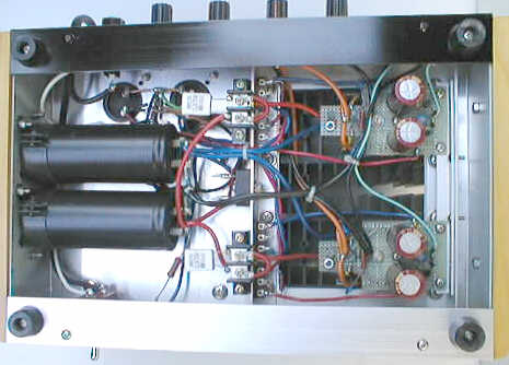
Just change a little wiring, the source follower circuit voltage circuits in the mirror can be changed.
Miller-voltage operating conditions of the basic design is satisfactory, the source follower to change to get high-quality sound.

USB DAC GC-PCM2706


USB DAC GC-PCM2706
As General of the computer sound card if the total effect is generally not very good, often wear headphones to listen to a lot of strange sounds, if you want to do-it-yourself USB DAC to make best results, a USB PCM2702 DAC chip, such as the PCM2706 and ...
I had the choice of PCM 2706PJT, the use of its flexible than the PCM2702, and SPDIF output can I2S, IT is a monster, was the only word regarded as a fundamental element of the PCM2706 to say whether the voice of their own if Otherwise, leave a fiberglass production that we have received and then the GC-CAD V2.0 are very good. I want to strengthen the function, right! Try it! However, as a result of recent time is not enough, I do not have the full demand Zhanyou added, only the strengthening of the next.
Plus BNC coaxial output, the Council received a suspension of the BNC. An increase in external power options, USB-General CAD is the use of USB directly to 5V power supply, but by the power of PC audio equipment may not always have the desired effect, I 'I am therefore of its external power supply, 3.3 V for the group 2 Power Supplies, a group of analog circuits for power, a group of digital circuits for power. COUNCIL PC and the lay-out discussion about the separation and a broken left on the hole, if you do not need external power, provided that it is broken, you can lower the volume.
The use of an external power L1117-3, the LDO 3V (voltage regulator IC), which is characterized by a low pressure difference, but only the best input voltage in the range of 4.8 to 6V, or I would during the process , The use of 12V DC adapter, power burn-L1117 at 3.3 V, burned on the exchange, burnt 7, the station is really great articles I bars.
The use of internal or external USB power to the circuit board to select Jumper, connect an external power supply for the employment of 1, 2, 2, 3 inserted in the internal use of USB power.
External power supply circuit left socket adapter, I had to stay 2 position, which one of you must also use their own elections in this direction for inserting the plug.
Fiber output can be used for the first TOTX178, 179,173, etc., fiber or compatible output of the first, I let you all types of electronic circuits in the first fiber-optic pin-compatible.
BNC BNC coaxial output is not directly in the main LAYOUT circuit board, I went to 2-pin, and then to people who can put on the chassis from outside the BNC or RCA Block.
As for the PCM2706 own production, I used the usual 3.5 mm headphone jack, if the direct use of computer speakers would be more practical, but it would be better received their best amplifiers.

Parts list is as follows:
R1, R2 ................................................ 15 Ω
R3, R4 ................................................ 22 Ω
R5, R6, R7, R8 ........................................ 3.3K
R9 .................................................... 1M
R10, R11 .............................................. 1.5K
R12, R13 .............................................. 330 Ω
R14 ................................................... 100 Ω

C1, C2, C3, C4 ........................................ 1uF/16V
C5,C6 C5, C6 .......................................... 47uF/16V
C7, C8 ................................................ 0.022uF (223)
C9, C10 ............................................... 100uF/16V
C11, C12 .............................................. 27P
C13 ................................................... 0.1uF grass-roots

U1 .................................................... PCM2706PJT
U2 .................................................... TOTX178 or compatible, and so on

LED ................................................... 3mmLED
L1, L2 ................................................ BEAD (core)
S1 ~ S7 ............................................... Small button switch
J1 .................................................... 3.5MM stereo headphone jack
J2 .................................................... USB-B-type outlet
CON1 .................................................. 2PIN pin Block
XTAL1 ................................................. Crystal 12Mhz
JP1, JP2 .............................................. 3PIN pin Block

Parts of the following non-necessary items, the use of an external power supply when the need for the following parts:
C14, C16, C18 ......................................... 100uF/16V
C15, C17 .............................................. 0.1uF grass-roots
P1 .................................................... 2.0mmDC Power Block
U3, U4 ................................................ L1117-3.3V


Due to the use of two-panel design, so even if you have to DIY circuit board, to be careful on the hole well, in the welding must also pay attention to board up and down side through the hole to connect, it is necessary to carefully, one by one spot , The top hole through the use of the welding I am fine copper (from the general removed the suspicious wire to the more than OK fine line), the first place through the hole and then welding, if there are places that hole capacitor, such as the outlet can not be double-sided The welding parts, but also to use such a lead through the first, in front of the hole to find places to foil next to the weld can not play other parts had to hole-blocking, if that hole is the resistance, the switch , And so on .. core, it can be a double-sided welding. If the plant is the system board, then of course there will be no hole through the problem.
In fact, such a small cost to achieve External computer audio, CP is a very high value, do not want to spend a lot of money, you want to burn the little DIY, can be said to be a good choice.
If you download the PDF file is in the next few pages, you can see the film circuit board files, printed automatically canceled when the zoom function to print 1:1.

Download PDF version: GC-PCM2706USBDAC-FL.pdf
Film file to download: PCM2706D-BL.pdf